
TL;DR: Toggle clamps are over-center hold-down devices in four basic flavors: horizontal, vertical, push-pull, and latch-action. Picking the right one is a balance of holding force, cycle life, and deflection. In auto and aerospace, that choice is constrained hard by IATF 16949 fixture validation and AS9100 FOD rules.
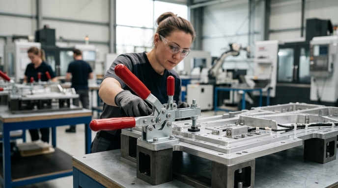
Why Toggle Clamps Still Dominate High-Volume Fixture Design
Toggle clamps still own high-volume fixture design because the over-center linkage gives you positive locking with zero continuous energy input. Once a manual or pneumatic toggle passes center, the reaction force from the workpiece actually drives the clamp tighter. It won’t back-drive under heavy machining or assembly loads, which is the whole point.
The cost gap versus zero-point systems or hydraulic swing clamps is enormous. Machinists on r/Machining regularly point out that an Enerpac-class hydraulic swing clamp runs $300 to $500 per clamping point, and that’s before you’ve bought a pump, valves, or any of the high-pressure plumbing. A Destaco 207-U manual vertical sits around $25.
Vacuum fixturing is great for flat, non-porous aerospace composites and useless on complex automotive body-in-white weldments. Toggle clamps give you the localized, high-pressure point contact needed to force stamped sheet metal down onto its datum locators. On automated lines, pneumatic toggles routinely clear a million cycles before preventive replacement, which puts cost-per-cycle into fractions of a cent.
Matching Clamp Geometry to the Assembly Task
Picking geometry comes down to operator ergonomics and tool clearance. The four main families (horizontal, vertical, push-pull, latch-action) each direct force differently and get in the way differently.
Vertical toggles like the Carr Lane CL-150-VTC have a handle that stands straight up when locked. Great for loading parts horizontally into the fixture, terrible if you’ve got overhead tooling. Horizontal clamps keep the handle flat in the locked position, which is why they’re the default on weld fixtures where a spot-welding robot needs to come down from above without a handle in its way.
Push-pull clamps drive a plunger straight forward. You spec these for pinning operations, or any time the reaction force wants to push straight back along the clamp’s own axis. Latch-action clamps pull two halves together — mold closures, composite layup clamshells, that kind of thing.
One thing engineers forget: manufacturers rate holding capacity at the base of the arm. Move the spindle out to the far end of a U-bar and effective clamping force drops in direct proportion to the lever ratio.
Holding Force Isn’t the Spec That Matters Most
Holding force is not the spec that drives part accuracy. Deflection under load and release repeatability are. The Destaco 207-U lists a max holding capacity of 375 lbs (1670 N), but apply 375 lbs upward against the spindle and the arm bends, lifting the workpiece right off its datum.
On a CMM fixture, allowable deflection is often measured in tenths of a thou. Arm bends, part shifts, part fails inspection, and nobody can figure out why the fixture that worked last Tuesday is suddenly scrapping cover plates.
Clamping force derates on a straight lever ratio:
Actual Force = (Rated Force × Distance from Pivot to Base) / Distance from Pivot to Spindle
A clamp rated for 400 lbs at 1 inch from the pivot drops to 200 lbs when you move the spindle out to 2 inches. You have to run that number against the actual reaction loads and the fixture’s deflection budget. Skipping this calculation is probably the single most common mistake I see on first-article fixture reviews.
Cycle Life Under Real Production Loads
Toggle clamps fail mechanically long before they fail catastrophically. In high-cycle auto stamping or welding cells, the dominant failure mode is pivot pin wear. The clamp cycles 50,000 to 100,000 times a year and weld slag plus airborne metal dust basically turn into lapping compound inside the pivot joints.
The pivot holes in the side plates ovalize.
That slop in the linkage means the clamp still locks over center, but the spindle no longer reaches its original depth. You lose clamping pressure gradually, not all at once, which is worse because nobody notices until the parts start drifting out of tolerance.
Run-to-failure economics almost never pencil out on a high-volume line. A $30 clamp failing in place can trigger a $5,000 line stoppage. Preventive replacement intervals are usually set by cycle count: standard manual clamps in dirty environments get swapped or rebuilt every 20,000 to 50,000 cycles, heavy-duty models with hardened steel bushings stretch that further, and pneumatic units running on clean lubricated shop air often go past a million cycles before the cylinder seals give up.
Pneumatic and Sensed Toggle Clamps for Automated Lines
Automated auto lines ditch the manual handle for a pneumatic cylinder. The Destaco 803, which is the pneumatic analog to the 207-U, gives you 600 lbs of holding capacity at a max cylinder pressure of 145 psig (10 bar).
Going pneumatic means you now need position sensing feeding back to the PLC. Inductive proximity sensors (Turck, Pepperl+Fuchs, the usual suspects) mount directly on the clamp cylinder and confirm the clamp is fully open before the robot loads a part, and fully closed before the weld cycle fires.
That sensing loop is your basic poka-yoke circuit. Load a part wrong, clamp doesn’t reach fully closed, sensor never triggers, PLC faults, machine doesn’t cycle, nothing crashes. Air consumption per cycle is tiny — anecdotally under 0.05 CFM per clamp — but you still have to size the supply lines so that pressure doesn’t sag when twenty clamps actuate at the same instant.
Aerospace-Specific Requirements (AS9100, FOD, Clean Assembly)
Aerospace demands captive hardware, FOD-safe coatings, and traceable serialization per AS9100 and NAS 412. The standard off-the-shelf toggle clamp has a spindle with two loose jam nuts. One of those backs out mid-shift inside a nacelle and you have a critical FOD event. Aerospace fixtures require captive spindles or thread-locking compounds, full stop.
Materials get regulated hard. Cadmium-plated clamps can’t go anywhere near titanium because of solid metal embrittlement risk. In CFRP layup zones, copper and zinc are usually restricted too.
The usual workaround is stainless, like the Destaco 207-USS, which gives you the same 375 lbs capacity without the plating-flake problem. AS9100D Clause 8.5.1 covers control of production equipment, and the fixtures (plus the clamps on them) have to be serialized, calibrated, and maintained on a schedule so they don’t quietly induce stress into a flight-critical component.
Automotive-Specific Requirements (IATF 16949, PPAP, Line-Rate Economics)
Automotive suppliers live under IATF 16949, which forces rigorous fixture validation during PPAP. If a fixture verifies part geometry, it’s treated as a gauge. That means the clamps have to deliver absolute repeatability to pass a gauge R&R study. A clamp whose seating pressure varies with operator fatigue will fail MSA, and then you’re redesigning the fixture under schedule pressure.
EV battery pack assembly layers on new constraints. Clamps holding modules have to be non-sparking and electrically insulating. A bare steel spindle sitting against a cell is asking for a short. Standard practice is to swap in neoprene-tipped spindles like the Destaco 207-201-A, which gives you a dielectric barrier and doesn’t mar the aluminum casing.
Line-rate economics usually win the ergonomics argument. If an operator is actuating twelve manual clamps per fixture, sixty times an hour, repetitive strain injuries are not a risk, they are an actuarial certainty. IATF 16949’s continuous improvement clauses tend to push those stations toward pneumatic sooner rather than later.
I’ll admit a bias here: I still spec manual clamps on low-volume aerospace cells even when the ergonomic math says go pneumatic, because the maintenance overhead of air lines and sensors on a cell that cycles 2,000 times a year isn’t worth it. Textbook answer disagrees. I do it anyway.
Selection Workflow — From Part Print to Purchase Order
The workflow is linear, if you discipline yourself to follow it. Establish the datum scheme from the part print. Calculate reaction forces from the machining or assembly process. Pick a geometry (horizontal, vertical, push-pull) that doesn’t foul tooling or the operator’s hands.
Then calculate required holding force with the derating applied for the actual spindle position. Evaluate cycle life — anything over 100,000 cycles a year, you’re specifying pneumatic or heavy-duty manual with hardened bushings. Last step is compliance: captive hardware for NAS 412, dielectric pads for EV.
Lead times are all over the map. Standard zinc-plated clamps from Destaco, Carr Lane, Jergens, or Good Hand ship off-the-shelf from McMaster or Grainger. The moment you ask for a specific stainless alloy, a custom arm length, or factory-installed sensors, you’re looking at 4 to 8 weeks. Plan the fixture build backward from that.
FAQ
What’s the typical cycle life of a heavy-duty toggle clamp in automotive production?
Manual toggles in a dirty weld environment usually make 20,000 to 50,000 cycles before pin wear starts eating your clamping force. Pneumatic clamps on clean air can go past a million.
Are toggle clamps acceptable for AS9100-compliant aerospace fixtures?
Yes, provided they meet NAS 412 for FOD prevention. In practice that means captive hardware, thread-lockers on anything that can back out, and material choices (usually stainless) that won’t flake plating or set up galvanic issues against the airframe alloys you’re touching. Serialization and a documented maintenance interval are also non-negotiable if the fixture is on the AS9100 equipment list.
When should I choose pneumatic over manual toggle clamps?
Over 100,000 cycles per year, any time you need PLC verification via sensors, or when operator strain becomes a real injury risk.
How do I calculate the actual clamping force at the bar tip?
Actual Force = (Rated Force × Distance from Pivot to Base) / Distance from Pivot to Spindle. The further the spindle is from the pivot, the less force you get.
Author Bio
Manufacturing engineer, ten-plus years in fixture design, tooling validation, and automated assembly integration for Tier 1 automotive and aerospace suppliers.
